Projects, etc.
.308 Winchester Bolt-Action Rifle
This project started at the end of my junior year of college, with the "simple" goal of designing and machining a functional bolt-action rifle receiver and bolt in the .308 Winchester (7.62x51mm NATO) cartridge. More important than building a rifle (I'm not particularly interested owning firearms, ironically), was to learn something about firearm design, safety, gunsmithing practice, and the failure modes for these machines. The basic concept of the bolt-action is so simple, I assumed the design aspect of this project would be almost trivial in design, and of easy-moderate difficulty in fabrication.
Soon the first rough Solidworks models were born (note, I'm not offering downloads of these files, as I don't want to be blamed if someone tries to copy my design and gets injured or killed because of it):
Soon the first rough Solidworks models were born (note, I'm not offering downloads of these files, as I don't want to be blamed if someone tries to copy my design and gets injured or killed because of it):
Incomplete Models
Little more than a week into the project, I thought I had complete plans and could begin sourcing material. A design review showed numerous technical issues with the first revision. Enough that the initial design was not worth continuing to pursue.
So I started over.
So I started over.
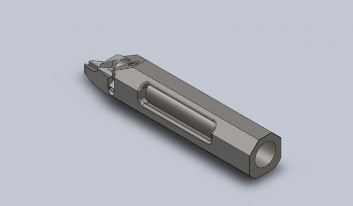
Note, the extraction cam and slot for the bolt are not drawn well here. My Solidworks has been having problems with the 'Solid Sweep' command.
Improved Design

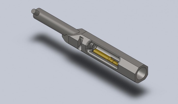
The second design was dramatically improved by careful reading of Stuart Otteson's The Bolt Action Rifle. With careful dimensions and a practicing engineer's analysis of a series of Mauser and Mauser-like actions at my disposal, the second revision was more precise, less chunky, and now included careful consideration of a number of safety and operational concerns, from feed-ramp design and extractor placement, to gas handling in case of case head failure.
Even with adequate reference to virtually copy the Remington 700 action, my design differs in a number of ways which compromise slightly increased weight for improved gas handing and machinability (no need for the use of a broach). The design is somewhere between a Mossberg 800, Weatherby Mark V, Remington 700, and Newton Rifle.
Even with adequate reference to virtually copy the Remington 700 action, my design differs in a number of ways which compromise slightly increased weight for improved gas handing and machinability (no need for the use of a broach). The design is somewhere between a Mossberg 800, Weatherby Mark V, Remington 700, and Newton Rifle.
12/30/2009 Machining
Soon came time to begin the machining. Work began with 3 feet of 1.5" 4140 steel and 3 feet of 1" 4140 steel. The 1" stock would make the bolts, and the 1.5" the receivers.
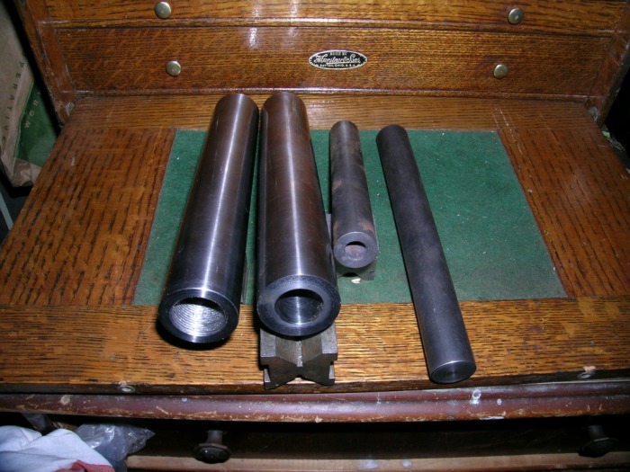
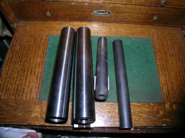
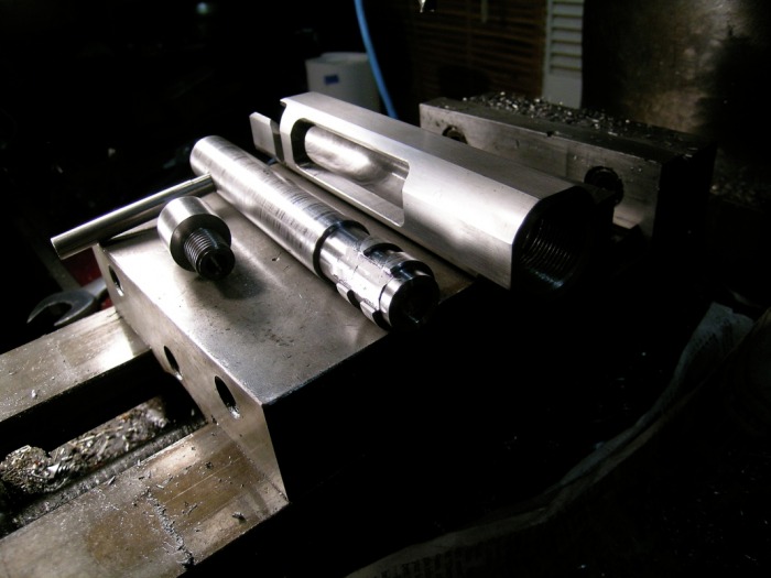
At left,the blanks for two receivers have been cut from stock, heat treated, and blind drilled for the bolt on the CNC lathe at work. The two blanks for the bolts have been sawed from stock. One was drilled for the firing pin before hardening, and the other was not. Both were turned to 15/16"OD and hardened, leaving 1/16" for machining to size.
At left,the blanks for two receivers have been cut from stock, heat treated, and blind drilled for the bolt on the CNC lathe at work. The two blanks for the bolts have been sawed from stock. One was drilled for the firing pin before hardening, and the other was not. Both were turned to 15/16"OD and hardened, leaving 1/16" for machining to size.

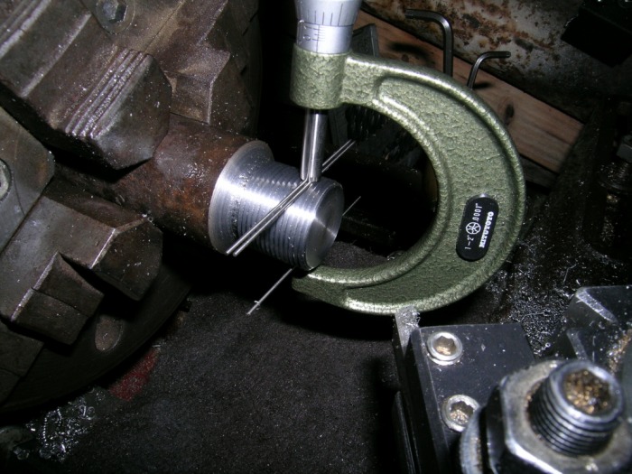

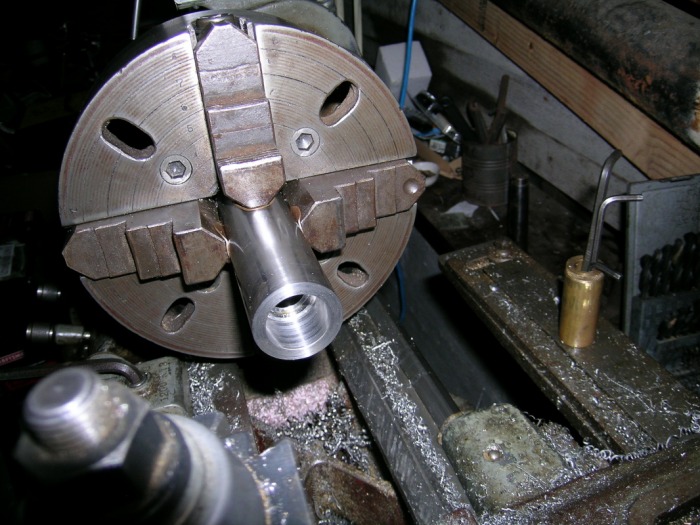
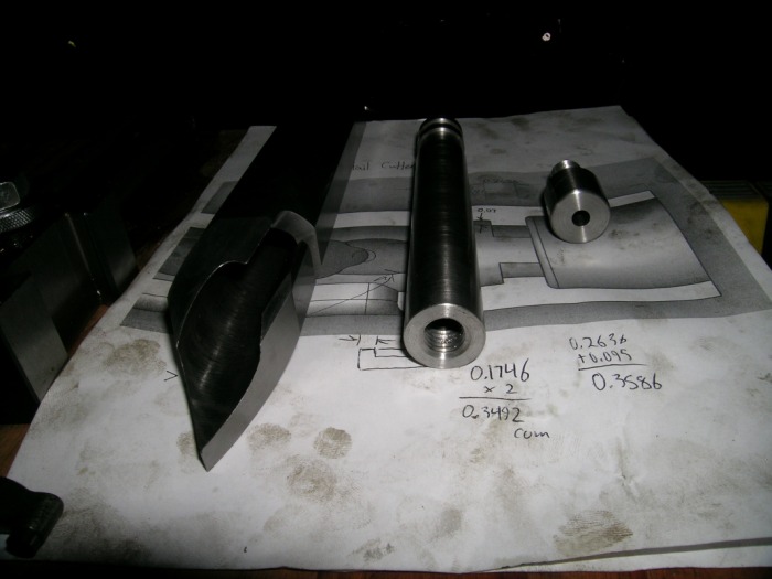
1/03/2010 ...And So Ended the Turning
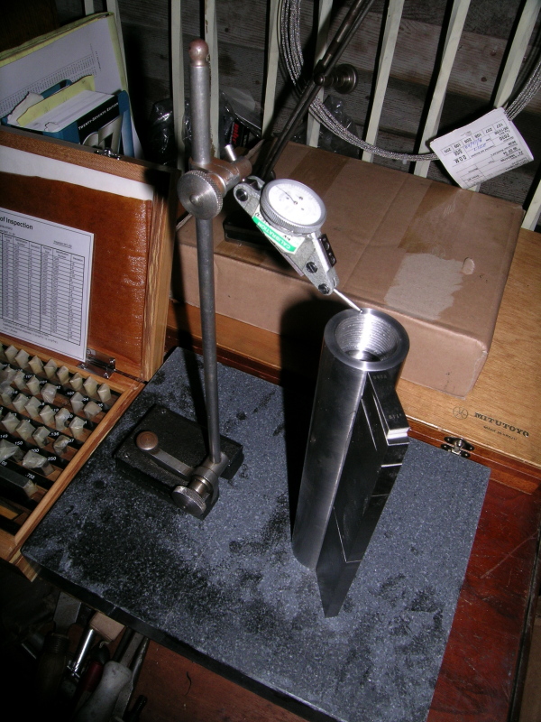
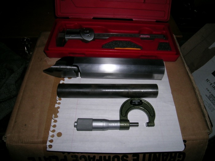
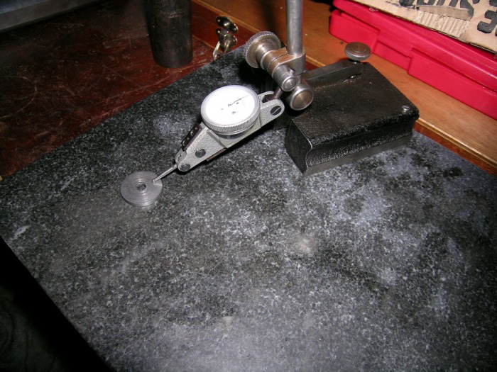
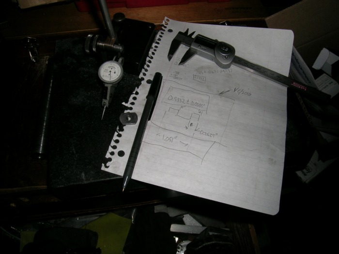
Lathe work consisted of facing both ends, drilling the bolt hole, and cutting the lug abutments and barrel threads. The picture attached is how I had to measure the length of the bolt, since I don't have any calipers with capacities greater than 6". As of this picture, bolt overall length is ~8.718" (the exact number is scrawled in a notebook down in the shop). The rectangular stack is a stack of gauge blocks, and that is a surface plate everything is sitting on. The indicator reads in 0.0005".
1/04/2010 Milling
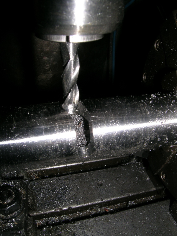
On completion of the turning, the milling of the receiver profile, lug abutments, bolt handle clearance, and extraction cam had to begin. The order of the machining of these features is critical, as the overall fit, function, and accuracy of the parts depends on the proper machining of each feature.
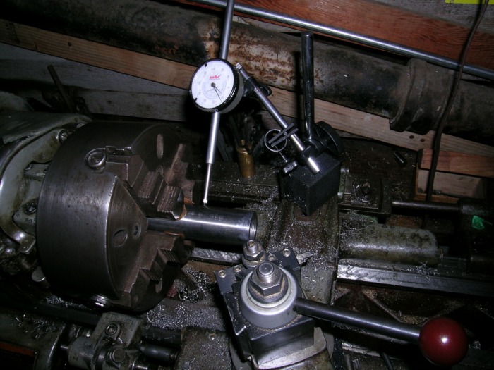
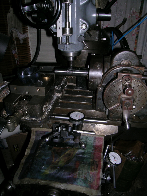
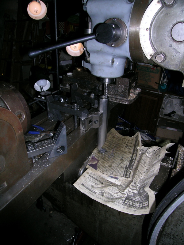
So first comes the milling of the bolt handle clearance and extractor cams, while the bolt is still round (and thus easy to hold in the 3-jaw chuck of the dividing head). Pictured at left is the setup I settled on, once again using dial indicators as the "poor man's DRO". The vise isn't touching anything, I was just too lazy to move it. I don't have a tailstock for the dividing head, but it would have been nice, as carbide endmills don't like chatter, and that metal is hanging out pretty far.
So first comes the milling of the bolt handle clearance and extractor cams, while the bolt is still round (and thus easy to hold in the 3-jaw chuck of the dividing head). Pictured at left is the setup I settled on, once again using dial indicators as the "poor man's DRO". The vise isn't touching anything, I was just too lazy to move it. I don't have a tailstock for the dividing head, but it would have been nice, as carbide endmills don't like chatter, and that metal is hanging out pretty far.


1/06/2010 "Progress"
Having spent about 2-4 hours per night on this project for ~11 nights straight, I decided to make a list of operations left to do on the action, with a full 9 days left to break (and thus access to my machine shop).
The list goes something like this, with "(H)" denoting a cut or fitting operation which I expect to be difficult.
Receiver:
-ejection/loading port
-sear groove
-trigger hanger clearance
-bolt guide slot
-assorted holes and threads (bedding screws, trigger hanger screws, bolt stop hole, etc.)
Bolt:
-lug milling (H)
-chambering cams (H)
-bolt handle threads
-cocking cam (including calculating firing pin fall...) (H)
-Ejector hole/threads
-Extractor milling (H)
-bolt guide groove/ramp
-gas vent holes
-bolt shroud threads
Bolt Shroud:
-threads
-sear clearance milling
-safety
Firing Pin:
-tip
-shoulder gas cuts
-threads
Sear/firing pin block:
-sear shaping
-threads
Bolt Stop:
Milling, drilling, checkering (?)
Things to order (or make?):
-firing pin spring
-woodruff cutter
In case it isn't evident, I have a ton of work left to do. Many of the operations listed above take easily 30-90 minutes to setup and run (remember, all machining is done manually, and I need to grind my own cutters at many points. This slows things severely). So, having made this list, if I get the bolt, bolt shroud, and receiver done by the end of break, I will be more than satisfied. The rest can be finished after graduation.
1/07/2010 More Lathe Work
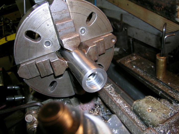
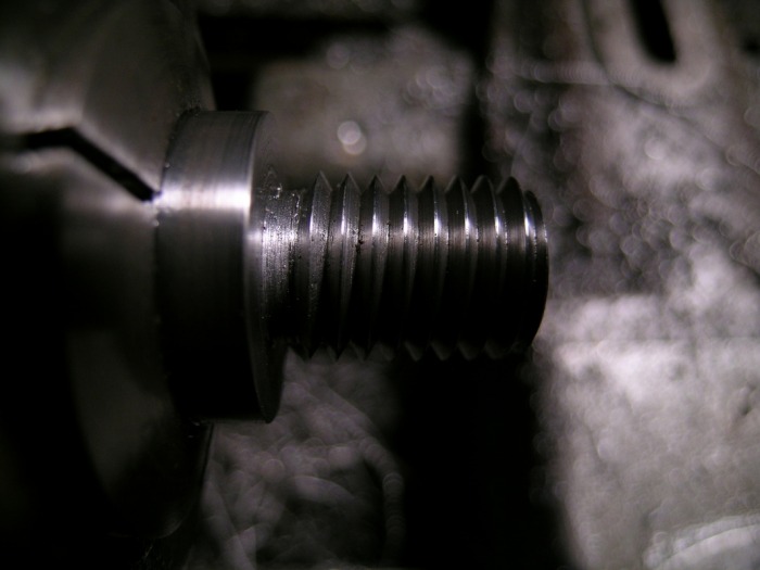
Tonight was time to thread the bolt to accept the bolt shroud, as well begin the bolt shroud itself. I had originally planned on milling clearance for the lug abutments and the chambering cams on the bolt lugs, but just as I setup the bolt in the dividing head, I noticed the cut I planned would compromise the breech, which is unacceptable. So I found a teeny (1/16") endmill which theoretically could solve my problems, but I'm hoping to borrow a dovetail cutter to do the same job.
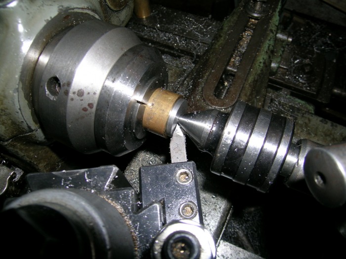
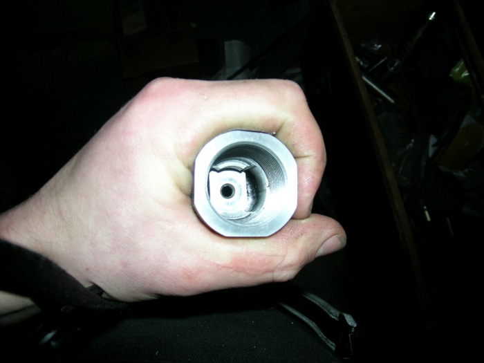
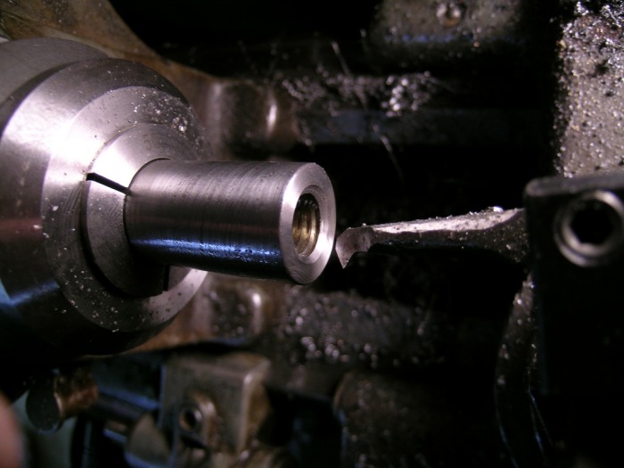
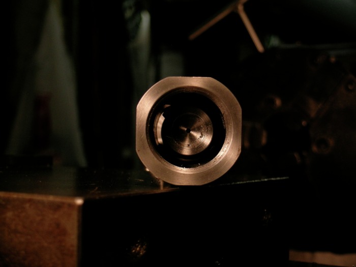
Pictured to the left is the boring bar used to cut the threads in the bolt for the bolt shroud. They are custom .567"-13 LH threads, made to clear the 7/16" hole for the firing pin spring (I also calculated firing pin fall for adequate striker energy. It agrees decently with what I've found in other references). The nice thing about LH threads is you can run the spindle forwards and thread away from a shoulder. So it was relatively easy to do these coarse blind shoulder internal threads, even with a fast spindle speed. The reason for the LH threads is to minimize the gap between the bolt shroud and bolt when locked, and maximize it as the bolt unlocks (if it were a lefty action, the threads would be RH). This keeps the action cleaner, as well as reduces the effort required to cock the firing pin spring. Dare I say an improvement over the Remington and Mauser actions?
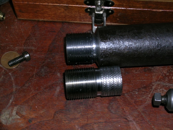
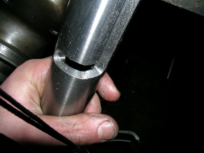
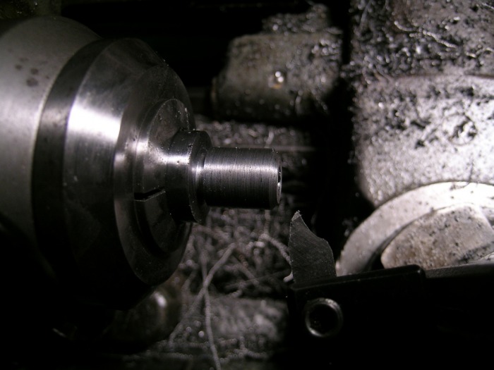
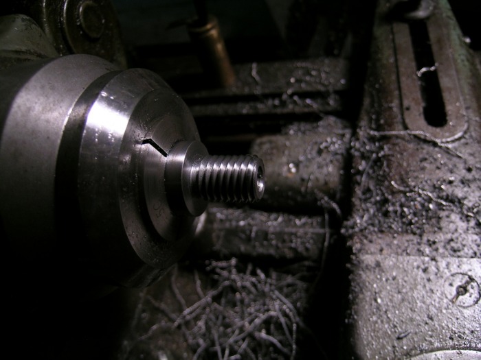
Pictured below are a couple of photos of the threading of the bolt shroud (and checking its fit in the receiver). The bolt shroud is annealed 4140. The stuff machines like crap, but whatever. It polished up OK-ish.
Pictured to the left is the boring bar used to cut the threads in the bolt for the bolt shroud. They are custom .567"-13 LH threads, made to clear the 7/16" hole for the firing pin spring (I also calculated firing pin fall for adequate striker energy. It agrees decently with what I've found in other references). The nice thing about LH threads is you can run the spindle forwards and thread away from a shoulder. So it was relatively easy to do these coarse blind shoulder internal threads, even with a fast spindle speed. The reason for the LH threads is to minimize the gap between the bolt shroud and bolt when locked, and maximize it as the bolt unlocks (if it were a lefty action, the threads would be RH). This keeps the action cleaner, as well as reduces the effort required to cock the firing pin spring. Dare I say an improvement over the Remington and Mauser actions?
Pictured below are a couple of photos of the threading of the bolt shroud (and checking its fit in the receiver). The bolt shroud is annealed 4140. The stuff machines like crap, but whatever. It polished up OK-ish.

1/07/2010 Current Progress
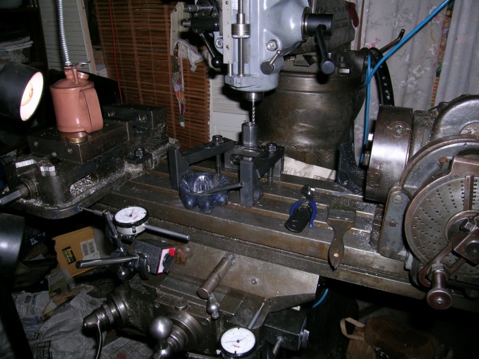
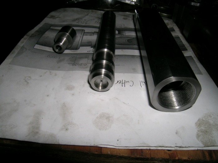
These are the components of the action, as they currently stand. It's coming along, but there's clearly significant work left...

1/16/2010 Final Progress and Pause
It's very hard to stop work on an unfinished project to go eat dinner, never mind how stopping for 4 months in order to finish school. But that's what's happened. This picture shows the action as it currently stands. Enough machining is done such that one can no "test cycle" the action, but there is still no firing pin, firing pin spring, extractor, ejector, or bolt guide. The receiver also lacks a slot for the trigger and a number of other critical features. My guess is there are another 10-15 hours of machining left to finish the action. Luckily there aren't too many difficult cuts left...


6/11/2010, Graduated and Back to Work

So I took a long break to finish college. It was the most merciful semester yet, and unless there's grad school in store for me, the last. It took a month after getting home to get back to work in the shop, since I was spending all my time at real work and applying for jobs. I'm not employed with a 9-5, which has its perks: Money, and it's downs: Lack of time. Still, there's always a little bit of time for the shop.
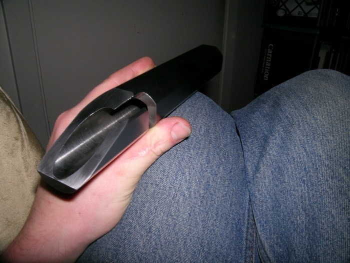
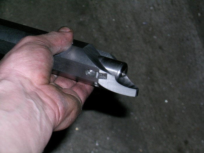
Anyways, back on topic... I spent a large part of this weekend working on the bolt guide/stop. The function is basic, but it took a surprising amount of careful design, machining, and hand fitting. The guide was milled out of a 1/2" OD piece of 304 s/s bar I had laying around. I want something that won't rust and is softer than the bolt (RC38), so 304 stainless is ideal.
Well, after a bunch of work on the stop, followed by careful hand-fitting and testing, I finally frilled the receiver for a spring plunger (I love these things) to make the stop follow the bolt guide groove. Then I milled the groove, and tested it. Success! Well, pictures don't do it justice, so just take my word for it. Most of the very, very difficult cuts are done, and here is all that is left (not the lack of "(H)" marks denoting difficult operations... They're mostly done!).
Receiver:
-sear groove
-trigger hanger clearance
-assorted holes and threads (bedding screws, trigger hanger screws, etc.)
Bolt:
-Ejector hole/threads
-gas vent holes
Bolt Shroud:
-threads
-sear clearance milling
-safety
Firing Pin:
-tip
-shoulder gas cuts
-threads
Sear/firing pin block:
-sear shaping
-threads
Bolt Stop:
Things to order (or make?):
-firing pin spring
