Projects, etc.
First Nested Cube

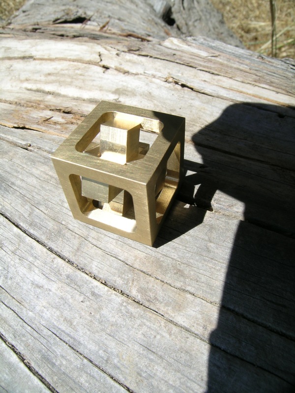
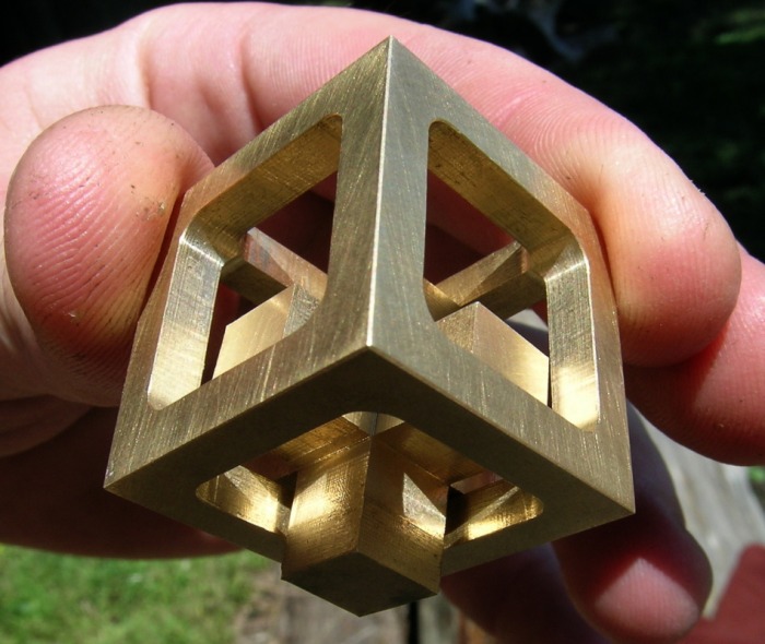
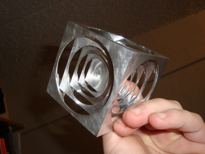
This project was undertaken on a bit of a whim. I had seen discussions of machining puzzles on various machining sites before, and had ideas on how I would do one of my own, but had never followed through. The one night in the summer of 2009, I suddenly decided to try. The cube pictured is 1±0.0005" on a side. The inner "jack" shape is trapped there. It was machined from 1.5" 360 round brass bar. Total machining time was around 5-6 hours, but I figure a second try would take under three hours. I gave this to my favorite math professor later in the year. Unfortunately I didn't document the making of this cube at all. Another couple of views of it are below.
A rough description of how the cube is made follows (if you have a cnc mill, the process is similar, you just don't have to stress about turning the cranks):
One needs a vertical milling machine (any mill, even as small as a Sherline, Taig, or Atlas horizontal will do. the instructions are for a vertical mill), 1/4" endmill, 1" or larger fly cutter (for making the initial cube), file and/or 400-600 grit sand paper (for deburring), a milling vise, and an edge finder. A digital readout or two 1" dial indicators are helpful, however I just used the graduated dials on my worn-out 50 year old bridgeport. The final part was good to within ±0.0015". You can probably do better.
First a very precise 1" cube is machined (I aimed for ±0.00025" on length and parallelism, and ±0.0005"/1" on squareness). The precision of this initial cube is critical, as the cube must sit the same in the fixture no matter its orientation.
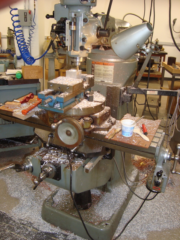
Next, a vise is setup in a vertical milling machine (make sure the back jaw is parallel to the x-axis and the spindle is square to the table) with a work stop on the back jaw (indexing the cube's position along the x-axis). Not having a vise stop, I used a piece of scrap aluminum c-clamped to the back vise jaw. The only important thing is that the stop not move and bear on a part of the cube which is not going to be machined off later. You can get by without a stop by edge-finding the cube every time you rotate it, but this will take ages.
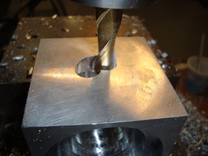
Now place the cube in the vise, up against the stop. Now, using a 1/4" endmill (I chose 1/4" so that the cube would be even: the center square will be 1/4" wide, the edges will be 1/8", and the cutout will be 1/4" on each side), cut out a square centered on the cube's face which is 1/2" wide, measured on tool center (thus 3/4" wide on the outside square, and 1/4" on the inside). Cut to 0.3750" depth. Don't be sloppy with these dimensions, as the bottom of this cut will be the side of another cut, and vice-versa. Here, the more accurate your initial cube and your handling of the machine is, the nicer the result will be.
Once you are done with the above cut, repeat the same cut five more times on each remaining face. On the final cut, don't be too aggressive with the milling, as the center free piece will not be held very tightly. That is where a good quality vise and well machined, parallel faces will come in, as they will help assure that both free pieces of the part are held firmly.
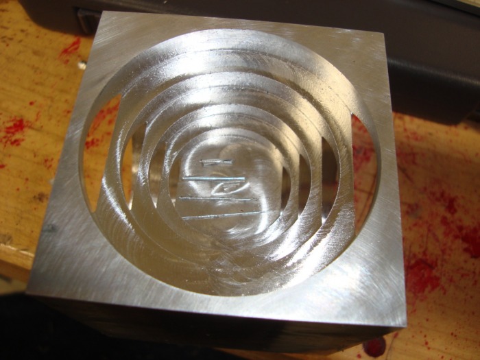
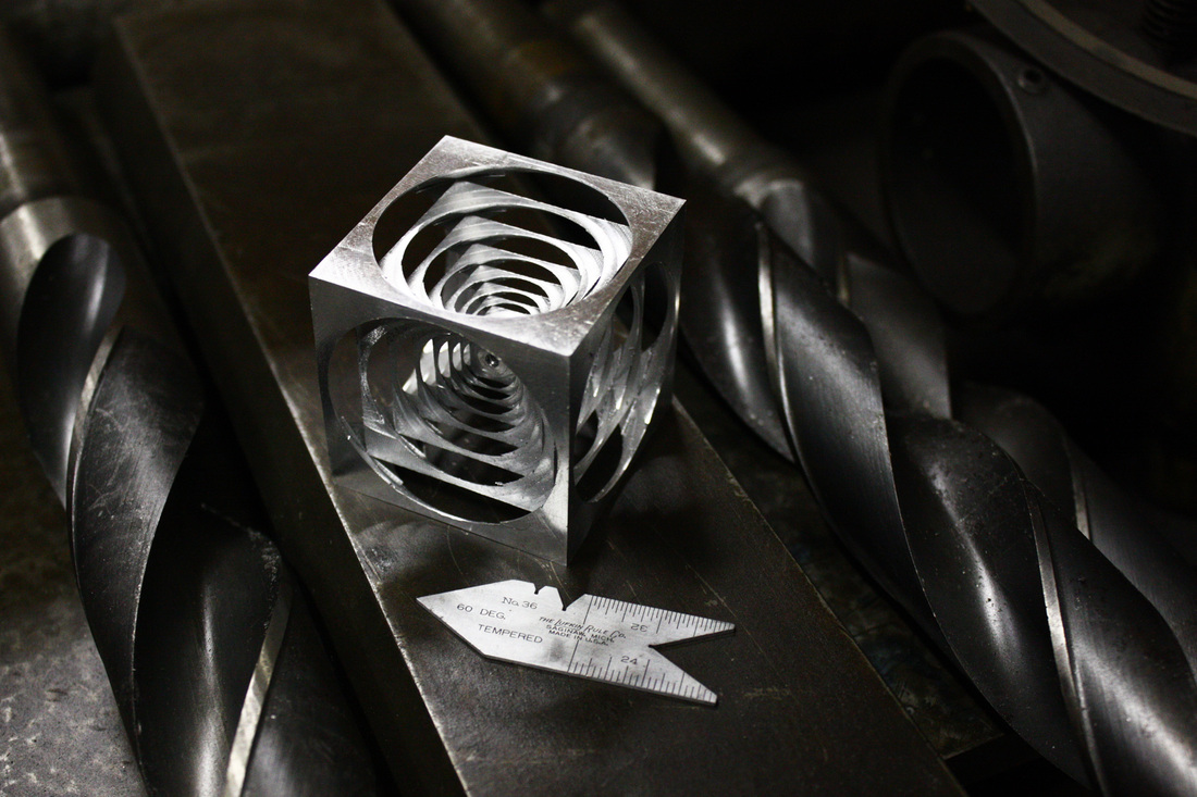
Then you are done. With the dimensions I provided, the cube should look similar to what is pictured, and not come out. Increasing endmill size can change that, however. One note, this project will really teach you to remember which way to crank the handle to feed the table on your mill, in case you don't already know that (on most machines, clockwise moves the table away from the handle, but there are exceptions). Getting this wrong in one of the corners can ruin the part and/or break the endmill.
A rough description of how the cube is made follows (if you have a cnc mill, the process is similar, you just don't have to stress about turning the cranks):
One needs a vertical milling machine (any mill, even as small as a Sherline, Taig, or Atlas horizontal will do. the instructions are for a vertical mill), 1/4" endmill, 1" or larger fly cutter (for making the initial cube), file and/or 400-600 grit sand paper (for deburring), a milling vise, and an edge finder. A digital readout or two 1" dial indicators are helpful, however I just used the graduated dials on my worn-out 50 year old bridgeport. The final part was good to within ±0.0015". You can probably do better.
First a very precise 1" cube is machined (I aimed for ±0.00025" on length and parallelism, and ±0.0005"/1" on squareness). The precision of this initial cube is critical, as the cube must sit the same in the fixture no matter its orientation.
Next, a vise is setup in a vertical milling machine (make sure the back jaw is parallel to the x-axis and the spindle is square to the table) with a work stop on the back jaw (indexing the cube's position along the x-axis). Not having a vise stop, I used a piece of scrap aluminum c-clamped to the back vise jaw. The only important thing is that the stop not move and bear on a part of the cube which is not going to be machined off later. You can get by without a stop by edge-finding the cube every time you rotate it, but this will take ages.
Now place the cube in the vise, up against the stop. Now, using a 1/4" endmill (I chose 1/4" so that the cube would be even: the center square will be 1/4" wide, the edges will be 1/8", and the cutout will be 1/4" on each side), cut out a square centered on the cube's face which is 1/2" wide, measured on tool center (thus 3/4" wide on the outside square, and 1/4" on the inside). Cut to 0.3750" depth. Don't be sloppy with these dimensions, as the bottom of this cut will be the side of another cut, and vice-versa. Here, the more accurate your initial cube and your handling of the machine is, the nicer the result will be.
Once you are done with the above cut, repeat the same cut five more times on each remaining face. On the final cut, don't be too aggressive with the milling, as the center free piece will not be held very tightly. That is where a good quality vise and well machined, parallel faces will come in, as they will help assure that both free pieces of the part are held firmly.
Then you are done. With the dimensions I provided, the cube should look similar to what is pictured, and not come out. Increasing endmill size can change that, however. One note, this project will really teach you to remember which way to crank the handle to feed the table on your mill, in case you don't already know that (on most machines, clockwise moves the table away from the handle, but there are exceptions). Getting this wrong in one of the corners can ruin the part and/or break the endmill.
Second (set of) Nested Cube(s)

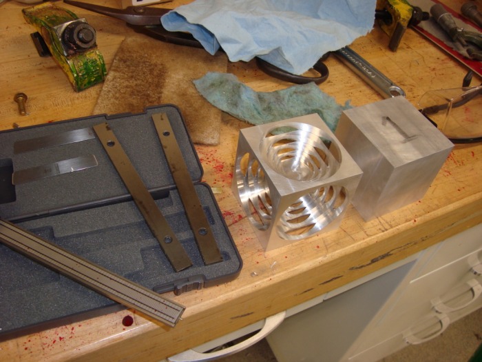
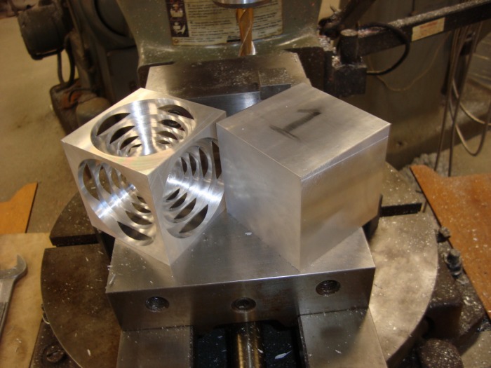
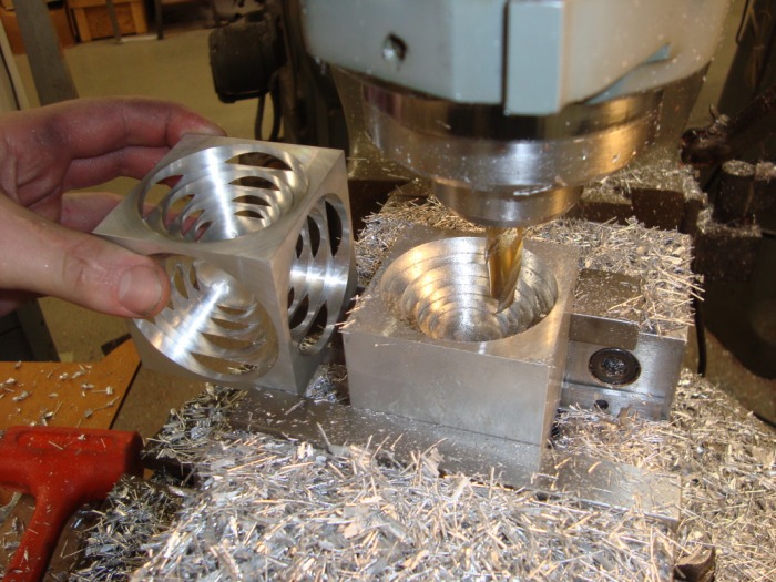
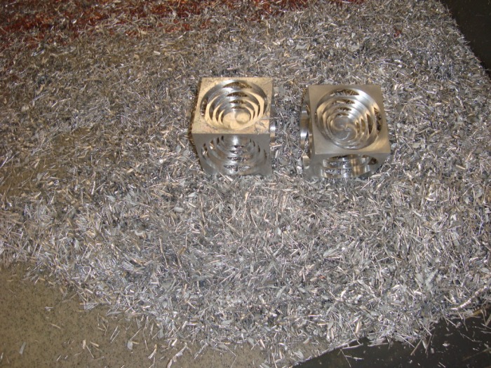
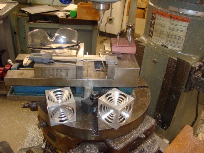
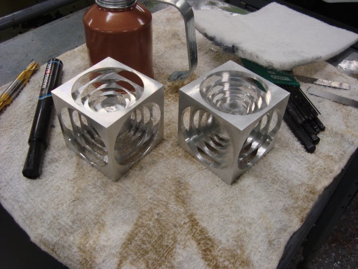
This set was started just before finals week in the fall of 2009 (my senior year). They took about 12-15 hours total for the both (that semester was the first semester I had ever had time for such a long project, even if I include fall, spring, and Thanksgiving breaks).
The bottom set is all attached, while the top set, each inner cube is free to move slightly within the next outer cube.
A photo album documenting the making of the second set of cubes is below. Click the photos to see captions. Note for the above project, having cnc machine tools doesn't really speed things up much. This project, however, is dramatically easier with cnc machine tools, simplifying both the setup and the actual machining.
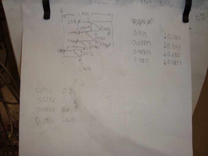
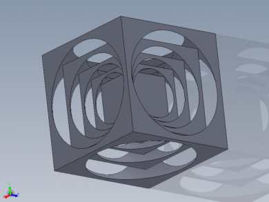
At the bottom of this page is a link to the Mathematica 6.0 script which I wrote to calculate the dimensions of each spherical cutout and cube. The photo of the solidworks model is a link to the Solidworks 2009 file of the nested cubes themselves.
The bottom set is all attached, while the top set, each inner cube is free to move slightly within the next outer cube.
A photo album documenting the making of the second set of cubes is below. Click the photos to see captions. Note for the above project, having cnc machine tools doesn't really speed things up much. This project, however, is dramatically easier with cnc machine tools, simplifying both the setup and the actual machining.
At the bottom of this page is a link to the Mathematica 6.0 script which I wrote to calculate the dimensions of each spherical cutout and cube. The photo of the solidworks model is a link to the Solidworks 2009 file of the nested cubes themselves.


Further Variations
One could combine the two cube projects above by putting the first project inside of the center cube on the second one. I might give that a shot sometime, depending on time. Of course it's also possible to continue the pattern of nested cubes farther, only being limited by cutter size, fixture accuracy, and operator patience. I figure with a 2.625" outside cube, I could have done 7 inner cubes instead of four, but cranking a rotary table that much is just tedious. You can decide how many you want to do...
The next step is to "stretch" the above cubes along one side, changing the cubes to rectangular prisms, and the spherical cutouts to ellipsoids. I have finished a Mathematica notebook for this, but haven't gotten around to making Solidworks models, yet. Unlike the models depicted above, this project almost necessitates a very specialized fixture or the use of a cnc milling machine.
Other tricks include a sphere within a cube, which is best done with either a form cutter or a radius attachment on a lathe. My first try with a form cutter, putting a 3/4" ball in a 1" aluminum cube ended with a snapped cutter. Someday, however.
Third Variation, End of 2012
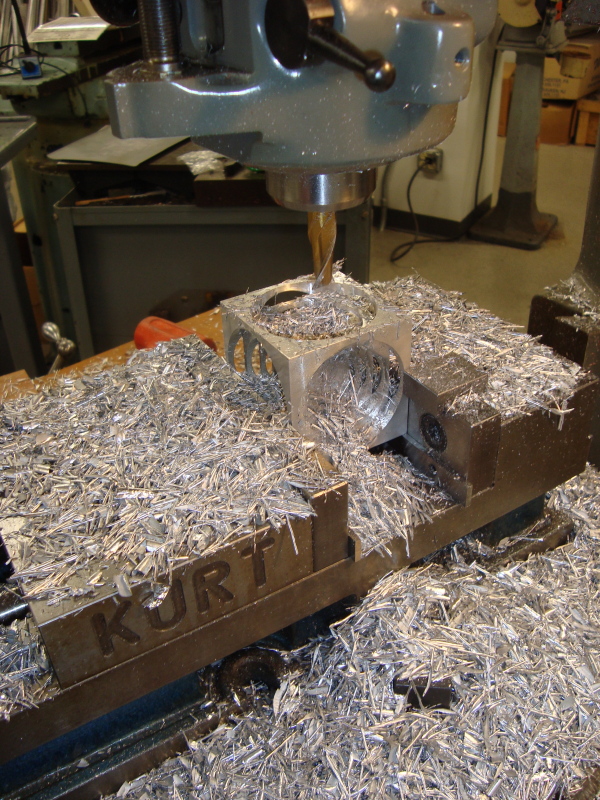
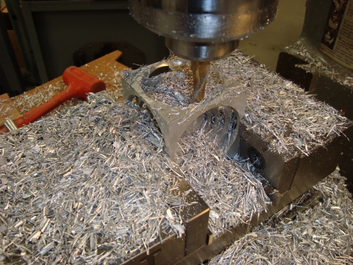
A friend and I decided to try CNC machining a set of nested cubes using my VMC and a CNC indexer. The cubes were completed in three setups and four operations, vastly faster than the previous version.
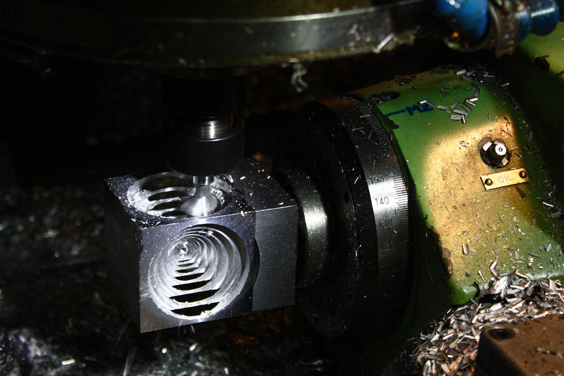
Showing the 3/4" dovetail cutter at work in setup #2, using the CNC indexer. The cubes were extremely delicate.
